Blog Archive

Wednesday 1 February 2023

Poor man's mattress for a Tesla (IKEA hack)


Poor man's custom mattress for a Tesla (IKEA hack) 


So I have been looking for a mattress for my Tesla Model Y (2023), and really the only two options for me are the DreamCase or Tesmat. 


DreamCase is way too expensive as I am only going to use it occasionally. And Tesmat looks like a good price point, but with shipping from the US to Norway it ends up being more than twice the price :( So both of these options are out for me.

I decided to try a regular 90cm IKEA mattress but it was not wide enough where the rear seating would be. Then I thought about inflatable ones, but here in Norway they cost USD170 for a crappy inflatable one. It was like the quality of a cheap pool lilo! No thanks.

Then I had an idea! So I purchased an Åsvang mattress (140x200cm) from Ikea. Here in Norway its like 120 bucks. Its 12cm thick, which isn't great but space in the car is limited. Too high a mattress and you can barely climb in as the roof is so much closer.


So here are the steps to create your custom mattress for your Tesla. 


Step 1 - Buy the mattress


*looks like the closest US equivalent is the IKEA Minnesund Queen mattress if I am not mistaken. Do your own research ;)


Step 2 - Unzip the cover, and turn to the smooth side.


Step 3 - I cut off a bit on the bottom (around 7cm) to make the total length 190cm. You can size it for your Tesla, but thats what I thought was right for the Model Y.


Step 4 - Measure the widths for your car at various points, always referencing the bottom of the mattress where the boot lid is. Mark it up with a marker.

I used a tape measure from top to bottom so I had an indication of vertical distance from the bottom. And then I used another tape measure to measure the width at various points.


Step 5 - Cut with a sharp bread knife. It's not the cleanest cut, so if you have an electric bread knife it will do a better job!


Step 6 - Zip it back up again and put it in the car. There is a bit of excess on the cover, but its not an issue and can be folded away. If you are the seamstress type then knock yourself out with a custom cover too :)


Step 7 - Profit $$$

Its actually pretty decent, and turned out better than I thought, as you get all of the available space. It does hang over the edge of the rear seats a bit, but not enough that its a problem. Of course your mileage may vary depending on the model. But I am very pleased with my Model Y poor mans mattress.


Step 8 - Fold it into the boot space when you are done sleeping.


Hope you liked the idea :)


(c) 2023 loiphin


Sunday 14 September 2014

Arduino Leonardo (ATMega32U4) based USB Volume control with mute - using a rotary encoder


This is a quick project I did with a clone Arduino Pro Micro (which I bought off eBay for peanuts). 


What you will need:


  • 1 x Arduino Leonardo or Pro Micro (any Arduino with a ATMega32U4 should work)
  • 1 x 10K resistor
  • 1 x rotary encoder with push button (I got mine from Adafruit  - http://www.adafruit.com/products/377 )
  • A couple of wires and a breadboard


Software libraries required:

You will need two libraries, one for the rotary encoder and one to produce the multimedia Volume Up/Down/Mute keys via USB

http://www.pjrc.com/teensy/td_libs_Encoder.html

https://github.com/NicoHood/HID

You will need to figure out how to install libraries within the Arduino IDE if you haven't done this before. Google is your friend.


Wiring:

I used pins digital pins 2 and 3 on the Arduino Pro Micro for the rotary encoder as they offer the best performance (interrupt driven). Try others if you like.

I used digital pin 10 for the push button part of the rotary encoder.


The rotary encoder has 5 pins. Three on one side and two on the other side. The group of 3 pins is used for the encoder itself. The two pins on the other side are for the push button switch inside the encoder. Wire the middle pin of the three (Pin 4 in diagram) to GND. Wire pins 3 and 5 of the encoder to digital pins 2 and 3 of the Arduino. If you like, you can swap pins 2 and 3 to make the encoder work in reverse (anti clockwise).

Connect pin 1 of the encoder to VCC on the Arduino. Wire pin 2 of the encoder to digital pin 10.

The 10K resistor is then connected from digital pin 10 to GND. This pulls the pin low.  Google more about pull-up/down resistors if you want to know more.


Wiring Summary:

Arduino VCC - Rotary Encoder Pin 1
Arduino Pin 10 - Rotary Encoder Pin 2
Arduino Pin 2 - Rotary Encoder Pin3
Arduino Pin 3 - Rotary Encoder Pin 5
Arduino GND - Rotary Encoder Pin 4

10K Resistor between Arduino Pin 10 and GND


The Code:

Just copy and paste the code below into an Arduino Sketch. It should work provided you have the Encoder and HID libraries installed.


// A small Arduino Leonardo based program which uses a rotary encoder to control the volume of a PC.
// Assumes the use of a rotary encoder with a push button, to allow muting.
// I used a clone Arduino Pro Micro (ATMega32U4), which are available for peanuts on eBay. 
//
// Use the code as you please - loiphin :)


#include <Encoder.h>
// The rotary encoder library http://www.pjrc.com/teensy/td_libs_Encoder.html

#include<HID.h>
// The HID library which produces the multimedia keys (Volume UP,DOWN and MUTE)  https://github.com/NicoHood/HID

int accel = 2;
// This is an acceleration factor. Use between 1 and 8 to suit how quickly the volume goes up or down.

int mutePin = 10;
// The digital pin to which the rotary encoder push button is connected too. Assumes that the pin has a pull-down resistor.

Encoder myEnc(2, 3);
// These are the pins to which the rotary encoder is connected.
// Pins 2,3 are the interrupt pins on a Leonardo/Uno, which give best performance with a rotary encoder. 
// Use other pins if you wish, but performance may suffer.
// Avoid using pins that have LED's attached.

long oldPosition  = -999;
int buttonState;
int lastButtonState = LOW;
long lastDebounceTime = 0;
long debounceDelay = 80;  // Button debounce time in millseconds. Increase if mute button doesnt work properly.


void setup() {
  pinMode(mutePin, INPUT);
  
  Serial.begin(9600);
  Serial.println("Debug Output:");
  
  Media.begin();
  
}


void loop() {
  long newPosition = myEnc.read() / accel;
  if (newPosition != oldPosition) {
    
    if(newPosition > oldPosition) {
      Media.write(MEDIA_VOLUME_UP);
    }
    
    if(oldPosition > newPosition) {
     Media.write(MEDIA_VOLUME_DOWN);
    }
    
    oldPosition = newPosition;
    Serial.println(newPosition);
    
  }
  
  // read the state of the switch into a local variable:
  int reading = digitalRead(mutePin);

  // check to see if you just pressed the button 
  // (i.e. the input went from LOW to HIGH),  and you've waited 
  // long enough since the last press to ignore any noise:  

  // If the switch changed, due to noise or pressing:
  if (reading != lastButtonState) {
    // reset the debouncing timer
    lastDebounceTime = millis();
  } 
  
  if ((millis() - lastDebounceTime) > debounceDelay) {
    // whatever the reading is at, it's been there for longer
    // than the debounce delay, so take it as the actual current state:

    // if the button state has changed:
    if (reading != buttonState) {
      buttonState = reading;

      // Toggle MUTE if digital pin reads HIGH
      if (buttonState == HIGH) {
        Media.write(MEDIA_VOLUME_MUTE);
      }
    }
  }
  
  // save the reading.  Next time through the loop,
  // it'll be the lastButtonState:
  lastButtonState = reading;
}


Enjoy! - Leave a comment if you are stuck and I will try to help


Sunday 9 March 2014

Topre Type Heaven - Go to hell SwiftKey


My Type Heaven actually works on an Android Phone. In my case an HTC One with KitKat.

Tuesday 2 July 2013

Brand new IBM Model M for sale - Danish/Norwegian ISO Key Layout


Brand new IBM Model M's from 1997-98. (Updated 12th Dec 2013)


All the pics above are of my personal IBM Model M. But I can take pictures of the others on request.


Brand new IBM Model M keyboard:

- This is the 1391407 model, ISO Danish layout but easily converted to Norwegian with a few keycap swaps
- Some were made in 1997 and some in 1998 by IBM at the Greenock plant in Scotland.
- Buckling spring switches
- Removeable outer keycaps
- PS/2 connector (can use an adapter to convert to USB)
- Drainage Channels

All SOLD - Sorry

I have a few of these babies for sale. Prefer to ship within Norway (I am near Oslo), but can do international. Send me an email and I will get back to you ASAP.....

Now you are probably wondering why you should trust me?!? Well I have been on eBay for the past 12 years and have an account in the same name (loiphin) and have over 400 positive feedbacks. I am more than happy to communicate through eBay to confirm its me.

And more than happy to meet up in person, so as to show you that all is in working order.


Thursday 20 June 2013

SOLVED :) - After your Windows 8 computer is shutdown, the damn USB devices still stay on.


I have a Corsair K95 keyboard, Corsair M65 mouse and a Razer Tiamat 7.1 headset. After shutting down the power on my rig, they would still have all their lights on. Now the power consumption doesn't bother me, but the bright lights at night do! And the fact that the keyboard lights attract the attention of my young children like moths to a flame. They then start banging on the keyboard and mess with my setup.


This problem has plagued me for over a year now (with a number of previous mice and keyboards), and I finally figured out how to fix it. Most of the posts I have found suggest enabling ErP in the BIOS. My Asus motherboard (P8Z77-V) has this option as shown below (under Advanced menu, APM...)


Note - this setting also disables things like Wake On LAN (WoL), and other means of power up as shown above.

This setting is supposed to disable any USB power after you shutdown. However no matter what, it didn't seem to make any difference. When I shutdown my rig, the gaming headset and keyboard were glowing like hell. I updated my BIOS to the latest version, and screwed around with a bunch of BIOS settings and nothing helped.

But it wasn't the BIOS causing the issue now, it was Windows 8!

In order to get this to work you need to make one small change in Windows 8:

Go to Control Panel ---> System & Security ---> Power Options and select "Choose what the power button does" from the menu on the left.


1. Select "Change settings that are currently unavailable"

2. Un-tick "Turn on fast start-up"

3. Save changes.

4. Power down and voila your pesky USB devices no longer stay powered on :) 

Thursday 30 May 2013

Seagate Barracuda ST2000DM001 doesn't like VMware ESXI 5.x


I have two Seagate Barracuda ST2000DM001 drives, one of which has been happily working away in my main gaming rig. The other was in my ESXI rig.

For months I was seeing weird issues with the drive. It would suddenly disappear from ESXI, and all my VM's would be left hanging as the datastore drive disappeared. I have tried this on ESXI 5.0 and 5.1.

Also I would see after a day or two of rebooting my ESXI server, that the drive would exhibit unusually high latency time of around 1000ms!

I have also tried my other ST2000DM001 out of my gaming rig and it too suffers the same issue. I also upgraded the firmware to the latest release (CC4H), but still made no difference.

The link to Seagate's latest firmware update:

http://knowledge.seagate.com/articles/en_US/FAQ/223651en

Eventually I gave up with using this drive in my ESXI rig, and am now using both as a software RAID0 setup in Windows 8, on my gaming rig.

I never did get to the bottom of why this drive does not work correctly with ESXI, but if you are reading this at least you know you are not the only one suffering the problem.

A number of people are suffering from this, and the issue seems to be independent of the SATA controller used.


Getting an IBM M1015 RAID Controller to work as a datastore with VMware ESXI 5.1 U1

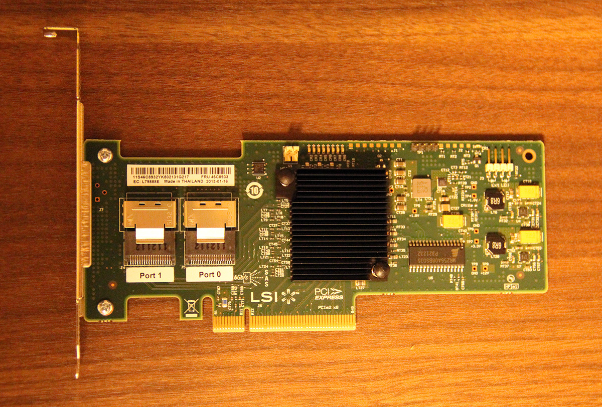
An IBM M1015 SAS / SATA 6GBps Controller with 8 ports (two SFF-8087 SAS connectors)


I recently upgraded my ESXI rig with a few new shiny bits and pieces:

Asus P9X79 WS motherboard
Intel E5-2620 2.0GHz Hex Core CPU
32GB DDR3 RAM

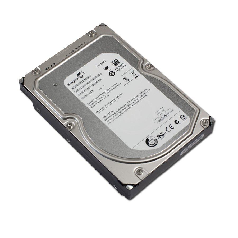
After setting it all up, I noticed my disk IO was pretty crappy, as all I had in there was a single old 1.5TB Seagate Barracuda SATA drive as a datastore. Now that the CPU and mobo were much faster, and running 6 or 7 VM's on a single drive, the disk side of things began to really struggle.

So I did a bit of investigation and ended up buying an IBM M1015 RAID Controller on ebay. It comes with 8 x 6GBps SATA/SAS ports, and RAID0,1,10. It is a rebadged LSI 9240-8i and is pretty much identical.

My goal is to run a RAID 0 stripe in ESXI as a datastore, in order to improve IOPS. I am not really concerned about redundancy or pass-through at this point.

You can upgrade the IBM M1015 with a special key to allow RAID 5, but I would not recommend it, as this controller in RAID 5 has rubbish write speeds of 20MB/sec! But in RAID0, which is what I intend to use it for, it just flies! I have read reports of people getting 2GB/sec read speeds using 4 x SSD's. Not bad :)


So my system currently is setup as so:

P9X79 WS mobo with latest 3401 BIOS (at the time of writing)
IBM M1015 flashed with latest LSI 9240-8i firmware and BIOS (20.11.1-0137 a.k.a 4.10 P2)
ESXI 5.1 Update 1


Initially when I plugged in the M1015 controller and booted ESXI, it gave me the the dreaded hang at the point of loading the megaraid_sas driver. See this post for more detail: 

http://communities.vmware.com/thread/397954?start=0&tstart=0

So then I started looking into cross flashing the M1015 into a LSI 9211-8i. The 9211-8i is pretty much the same thing as the M1015, as it uses the same SAS2008 chipset, but the support in ESXI is far better, as it uses a different driver than megaraid_sas.

To cut a very long story short, I could only flash the M1015 into a 9211-8i in IT mode. IT mode is basically an HBA, or a SATA controller with 8 ports. So no RAID :( And that's not what I wanted.

For some reason I could not flash the M1015 into 9211-8i IR mode, which is a basic RAID controller. It kept throwing up the "Chip in RESET state" error, despite trying about 6 different computers and a combination of DOS and UEFI shells.

If you are interested in going down this route, then please see this post:

http://www.servethehome.com/ibm-serveraid-m1015-part-4/


So I ended up rolling back to the original IBM M1015, by using the latest version of the LSI Megaraid 9240-8i firmware. Remember the M1015 is a rebadged 9240-8i and is identical, even the firmware. So it works just fine.

I followed the procedure of the above post, but used the latest firmware from LSI.

Convert LSI9211-IT/IR back to LSI9240 (IBM M1015)
Type in the following exactly:
Megarec -cleanflash 0
Megarec -writesbr 0 sbrm1015.bin
<reboot, back to USB stick>
Megarec -m0flash 0 0061_lsi.rom (for latest LSI firmware, also included 2x IBM roms too, just change name)
<reboot>
Done!


So I was still stuck between a hard place and a rock. I couldn't flash to 9211-8i IR mode and I couldn't seem to get ESXI to accept the card in its native M1015 (9240-8i) mode.

I found a number of posts talking about changing the "PCI Compatibility ROM" from Legacy ROM to EFI compatible ROM. The problem is that my motherboard (P9X79 WS) doesnt have this option (well, BIOS version 3401 doesn't have it)

Eventually I managed to figure out what to do to get the M1015 working in it's native mode!!!

On the Boot tab of the Asus P9X79 WS BIOS there is a CSM (Compatibility Support Module) section:

My settings are as follows:

Launch CSM - Enabled
Boot Device Control - UEFI and Legacy (You need Legacy to boot ESXI)
Boot from Storage Devices - UEFI or Legacy (This depends! - And I will explain why)

NOTE: Throughout the procedure I always had a separate SATA Drive as a boot drive for ESXI. I have not tried booting from the RAID array itself.

In order to initially configure your RAID array using the built in WebBIOS (Ctrl+H) when starting your machine, you need to have "Boot from Storage Devices" enabled as Legacy only.

Once you have configured the RAID array, you can then enter your mobo BIOS again and change the "Boot from Storage Devices" to UEFI. This step is very important as this is what allows ESXI to get past the megaraid_sas hang! For some reason ESXI needs it setup like this.

Also, you may be having issues trying to get into the WebBIOS initially to configure your array. You may have to do the following, besides the  "Boot from Storage Devices" enabled as Legacy only setting:

1. Machines boots up
2. Press CTRL+H to enter RAID array WebBIOS
3. Press F8 (for your boot menu) as soon as you see the normal machine BIOS screen
4. Select boot from RAID device (cant remember the exact wording)
Only then will it boot up into the RAID array WebBIOS. Crappy, I know, but it seems the only way to get into your RAID array, at least on my motherboard.

Also an optional thing, but nice to have... I downloaded the latest ESXI Megaraid driver from LSI, SCP'd it to my ESXI box in the /tmp folder. And then *SSH'd back into the box while it was in maintenance mode.

esxcli software vib install -v /tmp/scsi-megaraid-sas-6.506.51.00.1vmw-1vmw.500.0.0.472560.x86_64.vib --no-sig-check

*If you need to enable SSH access on your ESXI box:

1. Go to Home, Inventory, Hosts & Clusters
2. Highlight your ESXI host.
3. Choose the Configuration tab in the main window.
4. Choose Security Profile down the left hand side.
5. Choose Properties on the upper right corner of the main window.
6. Select SSH from the menu and choose Options.
7. Use the Service Commands button to Start or Stop the SSH process.


Hopefully this will help you get your M1015 working within ESXI :) Mine is purring away nicely with 4 x 750GB Barracuda drives.